You may work in partners or individually for this project.
Design a truss within the following constraints:
- 60 cm between supports
- Must withstand a force of 60 N, distributed evenly between whatever number of joints are in the middle 20 cm of the truss
- Must be a deck truss design, meaning that the top is flat with the truss structure extending below. The loads will act downward onto the flat top of the truss.
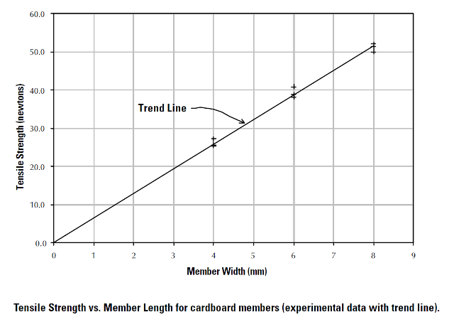
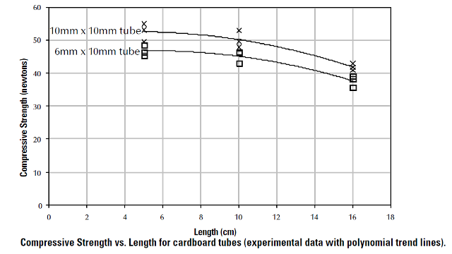
- Must be designed out of cardstock (file folder) members. You can either use 6 mm x 10 mm box tubes, 10 mm x 10 mm box tubes, or strips (for tensile loads) of any width you choose.
- There is a maximum length of the box tubes: see the graph. You can only use tubes up to the maximum tube length for which you have strength data.
- Tensile load strips can be any length, because tensile strength is not dependent on the length of the member.
Deliverables That You Turn In
- Use a truss solver to get solutions for your designs, such as MDSolids or Autodesk Force Effect (free app for Android or Chrome)
- Do your design work in your engineer’s notebook. You will get a grade out of 25 points for your notebook work.
- The notebook should have multiple pictures of trusses to show that you tried a whole bunch of possible solutions to the problem.
- For each design, add some text to discuss the design. Why did you try this design? How did you like the results? Did it fail to satisfy one or more constraints? Even if this design didn’t satisfy every goal, what were some advantages of this design? What are you going to try next?
- After you have your design finalized, list the size of tension and compression beams your bridge will be built out of.
Credit for this design project goes to Stephen J. Ressler, P.E., Ph.D. of the United States Military Academy. The graphs above and the general parameters of the project are taken from his excellent book on file folder bridge design.